Blueprint-style overview of the 7-bit processor co-design workflow linking VHDL hardware, ASM/Python software, and the CPU datapath

A Practical 7-Bit Processor with a Python Assembler

Estimated Reading Time: 16 minutes

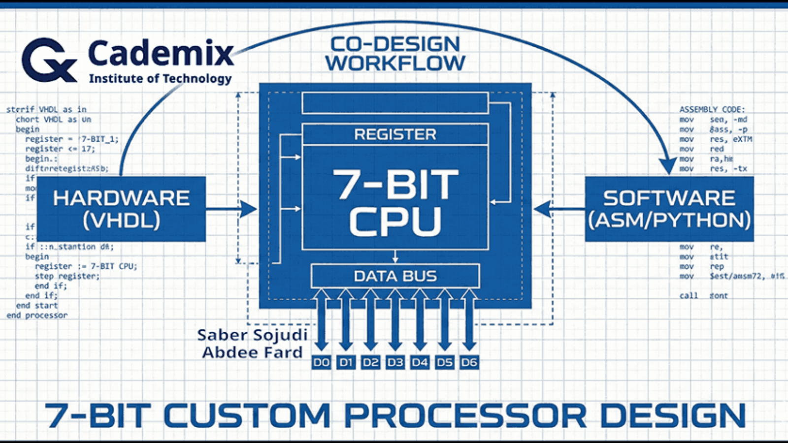
I built a compact 7-bit processor to explore hardware–software co-design end-to-end: defining a minimal instruction set, implementing the datapath and control in VHDL, and closing the loop with a small assembler that produces ROM-ready binaries. The design focuses on a small core of operations LOAD, ADD, SUB, and JNZ with an extended MULTIPLY instruction implemented using a shift-and-add approach to keep the hardware simple. Internally, the processor is decomposed into familiar blocks (ALU, register file, program counter, instruction register, ROM, and multiplexers), with a control unit described as an ASM-style state machine that sequences fetch, decode, and execute. A four-register file (R0R3) and a zero flag provide the minimum state and condition mechanism needed for basic control flow. To integrate software with the hardware model, I use a Python-based assembler that converts assembly-like inputs into the binary encodings expected by ROM initialization. The project is intended to be validated in simulation by observing program counter progression, register updates, and ALU outputs under representative instruction sequences.
Saber Sojudi Abdee Fard

Introduction

I designed this project to practice hardware–software co-design in a setting small enough to reason about completely. The core idea is straightforward: define a minimal instruction set, implement a complete processor around that ISA in VHDL, and connect it to a simple software tool a Python assembler that produces the exact 7-bit encodings the hardware expects. The result is an offline simulation workflow where I can iterate on both sides of the boundary: instruction semantics in hardware and program encoding in software.

The processor is intentionally constrained. Both data and instruction representations are 7 bits wide, and the ISA is limited to a small set of operations: LOAD, ADD, SUB, JNZ, and an extended MULTIPLY. Memory is ROM-based, and the goal is correctness and clarity in simulation rather than breadth of CPU features or performance. Within that scope, the design targets a complete “compile -> encode -> load -> simulate -> inspect” loop: compiling and simulating the VHDL modules, translating an assembly-like program through Conversion.py, loading the produced binary into Memory.vhd, and then validating behavior by inspecting the program counter, register updates, and ALU outputs in the simulator.

This article explains the system the way I worked with it: as a set of contracts between modules and between software and hardware. I focus on the architectural decomposition (datapath and control), the encoding boundary enforced by the assembler, and what constitutes a successful run in simulation. I also call out the explicit non-goals such as advanced control-flow features, richer memory models, or microarchitectural optimizations because the constraints are part of what makes the design teachable.

Methodology

Architecture overview

I implemented the processor as a small set of composable VHDL building blocks connected around a single 7-bit internal bus. The top-level entity (Processor) exposes CLK and RESET inputs and exports the four general-purpose register values (R0outR3out) specifically to make simulation inspection straightforward.

Inside Processor.vhd, the datapath is wired as follows:

  • A ROM (Memory) outputs a 7-bit word (MData) addressed by the program counter output (PC_OUT).
  • Two 4-to-1 multiplexers (MUX4x1) select ALU operands from the four register outputs (ROUT0ROUT3). Each mux is driven by a 2-bit selector (S0 for operand A, S1 for operand B).
  • The ALU computes a 7-bit result (ALURes) based on a 2-bit command (CMD).
  • A 2-to-1 “bus mux” (MUX2x1) selects what drives the shared internal bus (BUSout): either ROM data (MData) or the ALU result (ALURes), controlled by BUS_Sel.
  • The shared bus is then assigned to a single internal input (RIN <= BUSout) that feeds every state-holding element: the four registers, the instruction register (IR), and the program counter (PC) load their next value from RIN when their respective load control is asserted.

This wiring creates a clean contract boundary: computation happens in the ALU, storage happens in registers/IR/PC, and the only way values move is by selecting a source onto the bus and latching it into a destination on the next clock edge.

A control unit (control_unit) sits beside the datapath. It consumes the current instruction (ROUTIR, the instruction register output) and per-register zero indicators (ZR0ZR3), and it drives all load/select signals: LD0LD3, LDIR, LDPC, INC, BUS_Sel, plus the ALU command (CMD) and the two operand selectors (Sel0, Sel1).

Block diagram of the 7-bit CPU showing ROM, PC, shared RIN/BUS, register file, operand muxes, ALU, and control-unit signals

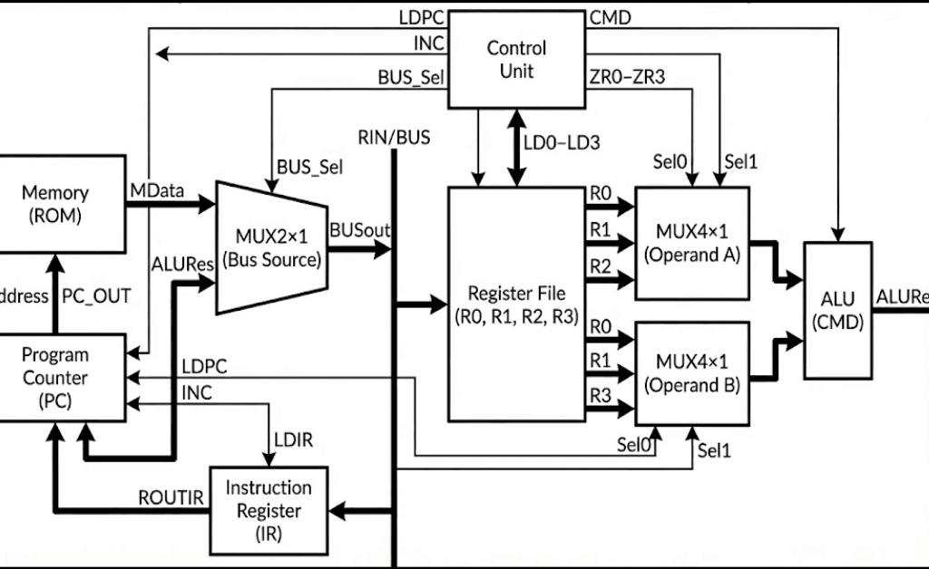
Figure 1 — The ROM, register file, and ALU are connected through a single bus-source mux that drives a shared internal bus (RIN), while the control unit sequences selects and load-enables for fetch and execute.

Control unit and instruction sequencing

I implemented the controller as an explicit enumerated-state machine in control_unit.vhd. The control unit decodes two fields from the 7-bit instruction:

  • y <= ROUTIR(6 downto 4) as a 3-bit opcode.
  • x <= ROUTIR(3 downto 2) as a 2-bit register selector (converted to an integer Reg_num for indexing the zero-flag vector).

The control flow uses these states (as defined in the state type): S0, S1, D, S2, S3, S4, S5, S6, S7, and S8. Operationally, they map to a compact fetch–decode–execute loop:

  • Fetch (S0): the controller asserts LDIR <= 1 while selecting ROM data onto the bus (BUS_Sel <= 0). In the same state it asserts INC <= 1 to advance the PC. Conceptually, this state is responsible for “IR <- M[PC]” and “PC <- PC + 1”.
  • Stabilize (S1): the controller deasserts INC and LDIR and transitions to decode.
  • Decode (D): the controller either halts, dispatches to an execute state based on y, or evaluates a conditional branch using the selected register’s zero flag.
    • A literal all-ones instruction (ROUTIR = "1111111") is treated as halt and transitions into S2, which self-loops.
    • If y = "000", it dispatches to Load (S3).
    • If y = "001", it dispatches to Add (S4).
    • If y = "010", it dispatches to Sub (S5).
    • If y = "100", it dispatches to Multiply (S8).
    • Otherwise, it treats the instruction as a conditional PC control operation that consults ZR(Reg_num) and chooses between S6 (load the PC) and S7 (skip).

The execute states drive the datapath in a very direct way:

  • Load (S3) asserts exactly one of LD0LD3 based on x, keeps the bus sourcing from ROM (BUS_Sel <= 0), and asserts INC <= 1 before returning to fetch. This matches a “load immediate/data word from ROM and step past it” pattern.
  • Add/Sub/Multiply (S4, S5, S8) select registers into the two ALU operand muxes (Sel0, Sel1), set CMD to the operation code ("00" for add, "01" for sub, "10" for multiply), switch the bus to the ALU result (BUS_Sel <= 1), and assert one of LD0LD3 to latch the result back into a register. In the current implementation, both operand selectors are derived from the same instruction field (x and ROUTIR(3 downto 2)), so both Sel0 and Sel1 are driven from the same two-bit slice.
  • PC load (S6) asserts LDPC <= 1 while selecting ROM data onto the bus (BUS_Sel <= 0) and returns to fetch. In combination with the top-level wiring (ROM addressed by PC_OUT, bus sourcing from MData), this implements an indirect jump target read: the PC loads the 7-bit word currently stored at the ROM address.
  • PC skip (S7) asserts INC <= 1 and returns to fetch. This acts as the complementary behavior to S6: when the condition is not met, the controller advances past the jump operand word.

That last pair (S6/S7) is a key contract in the design: conditional control flow is implemented by placing a jump target word in ROM immediately after the branch instruction, then either loading the PC from that word (taken) or incrementing past it (not taken). This keeps the instruction format small while still enabling label-based control flow at the assembly level.

Datapath components and local contracts

I structured the datapath around a small number of synchronous state-holding elements (registers, program counter, instruction register) and purely combinational plumbing (multiplexers and the ALU). The shared internal bus (RIN) is the only write-back path: every storage element loads from the same 7-bit value when its load-enable is asserted. That design choice keeps the movement of data explicit each cycle is “pick a source onto the bus, then latch it into one destination” which makes it straightforward to debug in simulation.

Register file and zero flags (Reg.vhd)

Each general-purpose register is implemented as a simple rising-edge latch with a load enable. The register stores a 7-bit vector (res) and continuously computes a per-register zero flag ZR. In this implementation, ZR is asserted high when the register content is exactly 0000000, and deasserted otherwise. Because the zero flag is derived from the stored register value (not the ALU result), conditional control flow is defined in terms of “what is currently in the selected register,” which is a clean contract for a small ISA.

A practical implication of this choice is that the condition mechanism is transparent to inspection: in simulation, I can interpret the branch condition by looking at the register value and its corresponding ZR* signal without needing an additional flag register.

Program counter semantics (PC.vhd)

The program counter is another 7-bit state element with three control inputs: CLR (asynchronous clear), LD (load from the bus), and INC (increment). The implementation uses a single internal accumulator (“inBUS” inside the clocked process) that can be loaded and incremented in the same cycle. If both LD and INC are asserted on a rising clock edge, the update order is “load, then increment,” which gives a well-defined behavior for any state machine that wants “PC <- operand + 1” rather than forcing two cycles.

In the top-level wiring, CLR is driven from the processor’s reset line (mapped through the RST signal), and the fetch phase relies on INC to advance sequentially through ROM addresses.

Instruction register (IR.vhd)

The instruction register is a minimal latch: on a rising clock edge, if LD is high, it captures the current bus value into an internal signal and exposes it as ROUT. There is no decode logic here by design; the controller consumes the raw 7-bit instruction word. This separation keeps “instruction storage” distinct from “instruction interpretation,” which is useful when iterating on encodings during co-design.

Combinational multiplexers (MUX2x1.vhd, MUX4x1.vhd)

I used two mux types:

  • A 2-to-1 mux selects the shared-bus source. In the current design, S=0 selects ROM data and S=1 selects the ALU result. This switch is effectively the “read vs compute” gate for the entire machine.
  • A 4-to-1 mux selects ALU operands from the four register outputs. The selector is two bits wide, built by concatenating the select lines inside the mux and mapping "00", "01", "10", "11" to R0, R1, R2, R3.

Both muxes are purely combinational. That means the timing contract is simple: control signals must be stable in time for the selected value to propagate to the bus (or ALU inputs) before the next rising edge, where it can be latched by the destination element.

ALU behavior and truncation (ALU.vhd)

The ALU accepts two 7-bit operands and a 2-bit CMD:

  • "00" performs unsigned addition.
  • "01" performs unsigned subtraction.
  • "10" performs multiplication via a shift-and-add loop.

Internally, both inputs are resized to 14 bits to allow intermediate growth during addition/subtraction/multiplication, and the multiplication iterates over the bits of IN1: for each set bit IN1(i), the ALU adds IN2 shifted left by i into an accumulator. This is a direct, minimal-hardware way to express multiplication in behavioral VHDL.

The key architectural contract is at the output: the ALU always returns only the lower 7 bits of the 14-bit intermediate result. In other words, arithmetic is effectively performed modulo (2^7) at the architectural boundary. That choice is consistent with the project’s 7-bit scope, but it also means overflow is handled by truncation rather than saturation or flagging.

shift add multiply

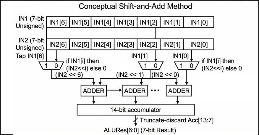
Figure 2 — Conceptual shift-and-add multiplication accumulates (IN2 << i) for each set bit IN1[i] into a 14-bit sum, then returns only the lower 7 bits as ALURes[6:0].

ROM and “program as VHDL” workflow (Memory.vhd)

The memory is implemented as a 128-entry ROM (instruction(127 downto 0)), addressed by the 7-bit program counter. The output is a direct combinational lookup: Data <= instruction(to_integer(unsigned(address))). The ROM contents are currently defined by assigning specific indices inside the VHDL architecture. This matches your intended workflow: use the Python assembler to generate 7-bit binary instruction words and then paste those encodings into Memory.vhd to run them in simulation.

The file also includes multiple annotated program variants. One example sequence is commented as an “add 7 with 4” demonstration, and another is structured as a small loop intended to exercise conditional branching and repeated arithmetic. A third variant (commented out) is positioned as a “hardware focus” multiplication path, contrasting with the loop-based approach. From an engineering perspective, keeping these snippets inline makes the simulation loop fast, but it also means “program loading” is manual and tightly coupled to the ROM source code rather than being a separate artifact (e.g., a memory initialization file).

Figure placement: A code figure that shows a short ROM snippet (a few consecutive instruction(i) <= "......."; lines) is useful here to make the “assembler output -> ROM initialization” boundary concrete.

Assembler and the hardware–software boundary

To make the processor usable as a co-design exercise rather than a pure hardware artifact, I included a small Python assembler (Assembler/Conversion.py) that translates assembly-like lines into binary strings that can be loaded into the ROM. The intent, as documented in the repository, is to run the conversion step first, then paste the produced encodings into Memory.vhd, and finally validate behavior in simulation by inspecting the program counter, register values, and ALU outputs.

The current assembler implementation is deliberately minimal: it tokenizes each line by removing commas and splitting on whitespace, looks up an opcode mnemonic in a small table, and then encodes operands by type. Register operands (R0R3) are encoded as 2-bit binary values, while any non-register operand is encoded as a 4-bit binary value. Each instruction line is therefore built by concatenating a fixed-width opcode field with one or more fixed-width operand fields, producing a binary string per line.

This assembler is also where the most important integration contract lives: the binary it emits must match the instruction word format the VHDL control unit expects. The README states the processor operates on 7-bit-wide instructions and provides an example encoding (ADD R1, R2 -> 0100010). In the current Conversion.py, however, the opcode table is 2 bits wide and only covers Load, ADD, SUB, and JNZ, with no explicit MULTIPLY support. In practice, that means the assembler represents the intended direction (software producing ROM-ready bits), but the exact bit-level encoding contract is something the project has to pin down consistently between README, assembler, and the VHDL decode logic. That “tight loop” of adjusting encodings until the fetch/decode/execute behavior matches expectations is part of the educational value of the co-design workflow.

Two targeted questions so I can describe the integration contract precisely in Section 6 (Results) and avoid guessing:

Key implementation notes

  • Source grounding: the narrative is based on README.md and the project snapshot you provided.
  • Entry points: hardware at src/Processor.vhd (top-level integration); software at Assembler/Conversion.py (assembly-to-binary conversion).
  • Core modules: src/ALU.vhd, src/control_unit.vhd, src/Memory.vhd, src/PC.vhd, src/IR.vhd, src/Reg.vhd, src/MUX2x1.vhd, src/MUX4x1.vhd.
  • Top-level integration: src/Processor.vhd instantiates and wires Reg, PC, IR, ALU, MUX4x1 (twice), MUX2x1, Memory, and control_unit, with a single internal bus (RIN <= BUSout) feeding all loadable elements.
  • Control surface: src/control_unit.vhd outputs LD0..LD3, LDIR, LDPC, INC, BUS_Sel, plus CMD, Sel0, and Sel1, and consumes ROUTIR and the per-register zero signals ZR0..ZR3.
  • Halt sentinel: the controller treats 1111111 as a dedicated halt instruction and transitions into a terminal self-loop state.
  • Reg.vhd: rising-edge storage with LD; ZR=1 iff the stored 7-bit value is 0000000.
  • PC.vhd: 7-bit counter with CLR (async clear), LD (load from bus), and INC (increment); supports “load then increment” if both asserted.
  • IR.vhd: rising-edge instruction latch controlled by LD.
  • MUX2x1.vhd: bus-source selector between ROM (I0) and ALU (I1) with a single select bit.
  • MUX4x1.vhd: operand selector over R0R3 driven by two select bits.
  • ALU.vhd: unsigned add/sub; multiply implemented via shift-and-add; output is truncated to the low 7 bits.
  • Memory.vhd: 128×7 ROM as an internal array with explicit per-address assignments; output is a combinational lookup addressed by PC.
  • Assembler entry point: assemble(assembly_code) consumes a multi-line string and returns a list of binary strings, one per parsed instruction line.
  • Assembler tokenization: commas are stripped (line.replace(",", "")), then tokens are split on whitespace; empty lines are ignored.
  • Assembler encoding: registers (R*) become 2-bit fields; non-register operands become 4-bit fields; the opcode is taken from opcode_table.
  • Assembler opcode coverage: Load, ADD, SUB, JNZ are defined; other instructions (including MULTIPLY) are not represented in the table.
  • Hardware inspection points: Processor exports R0outR3out explicitly, which makes it practical to validate instruction effects without adding extra debug modules.
  • Software-to-hardware boundary: assemble(...) emits binary strings from assembly-like lines; in the validated workflow these are used to populate the ROM in Memory.vhd.
  • Intended ISA surface: the README presents LOAD/ADD/SUB/JNZ plus an extended MULTIPLY, and frames validation as monitoring ALU output, register values, and program counter progression during simulation.
  • Documentation positioning: the README positions the project explicitly as a simulation-driven, educational processor build with a minimal ISA and a Python conversion step.
  • Encoding contract hotspot: the assembler’s opcode table and assemble(...) are the natural enforcement point for a single instruction-format contract once the bit layout is finalized.

Results

Because I did not build a dedicated VHDL testbench, validation for this project is based on interactive simulation: compiling the full design, loading a short program into the ROM, and then stepping the clock while inspecting the program counter, instruction register, control signals, ALU result, and the four register outputs. This approach matches the project’s educational scope: the primary outcome is a working hardware–software loop where I can translate assembly into binary, paste those encodings into the ROM, and observe the machine executing fetch–decode–execute in a waveform viewer.

Validation checkpoints

In practice, “success” in simulation is visible as a small set of repeatable checkpoints:

  • Fetch discipline: on each instruction boundary, the instruction register captures the ROM output while the program counter advances, yielding a stable next instruction word and a monotonic PC sequence.
  • Load path correctness: a LOAD sequence routes ROM data onto the internal bus and latches it into the selected register, so the register output changes exactly on the intended clock edge.
  • ALU path correctness: ADD and SUB route the ALU result onto the bus and latch it back into a register; the ALU output changes combinationally with operand selection, while architectural state changes only on clock edges.
  • Multiply behavior: the MULTIPLY operation produces a deterministic product consistent with a shift-and-add implementation, with the architectural output constrained to 7 bits (i.e., truncation on overflow) as part of the 7-bit design scope.
  • Conditional control flow observability: conditional branching is validated by correlating (a) the selected register value, (b) its zero flag, and (c) whether the PC is loaded from ROM or advanced past the next word. This makes the branch mechanism debuggable even without a testbench, because the condition and the control effect are both visible.

Artifacts produced

The durable artifacts from a run are simple but useful: (1) binary instruction words produced by the Python assembler and (2) waveform traces in the simulator that show the PC/IR/control/ALU/register timeline for a program. The repository also contains simulator-side artifacts (e.g., waveform databases) under src/, which is consistent with an interactive debug workflow rather than a scripted regression setup.

Discussion

This project’s strongest property is that it forces a clean interface between hardware intent and software representation. The processor design is small enough that I can reason about every signal transition, but complete enough to exercise real co-design constraints: instruction encoding decisions affect decode logic; decode logic constrains what the assembler must emit; and the ROM loading workflow becomes part of the “system contract,” not a separate afterthought.

That said, the absence of a testbench is a real limitation. Interactive waveform inspection is effective for bring-up and learning, but it does not scale to repeatable regression. Without an automated test harness, it is easy to introduce subtle contract drift for example, changes in instruction bit layout, operand field meaning, or zero-flag conventions without immediately noticing. The README asserts that the assembler “supports all implemented instructions,” but the current Conversion.py opcode table only enumerates Load, ADD, SUB, and JNZ, and it encodes operands into fixed 2-bit (register) and 4-bit (immediate) fields, which may or may not match the 7-bit instruction format you ultimately used in ROM. In a co-design project, this kind of mismatch is common and also instructive but it is worth surfacing as a deliberate boundary to tighten.

The architectural constraints are also doing real work here. The 7-bit width means arithmetic overflow is not an edge case; it is a normal mode of operation, and truncation becomes the implicit overflow policy. The ROM-based memory model similarly compresses the problem: by treating “program and data” as a static table, I avoid a full load/store subsystem and can focus on sequencing and datapath correctness. The cost is that the system is simulation-oriented, and “loading a program” is effectively editing VHDL. For the stated educational goal, that trade-off is reasonable, but it is the first thing I would change if I wanted this design to behave more like a reusable platform.

What I would tighten next

If I were evolving this beyond a learning artifact, I would prioritize three reliability-oriented improvements:

  1. Lock the instruction contract: define a single authoritative bit layout (fields, widths, and operand meaning) and make the VHDL decode and the Python assembler share it (even if only by generating a common table/module).
  2. Add a minimal self-checking testbench: one or two short programs with assertions on PC/register end state would turn interactive validation into repeatable regression.
  3. Separate program data from RTL: move ROM initialization into a file-based mechanism supported by the simulator (or at least generate Memory.vhd program blocks automatically from the assembler output) to reduce manual copy/paste drift.

Conclusion

I built this 7-bit processor as a compact hardware–software co-design exercise: a minimal ISA, a VHDL implementation with a clear separation between datapath and control, and a Python assembler that translates human-readable instructions into ROM-ready binary. The design is intentionally constrained 7-bit width, ROM-based memory, and a small instruction set so that the full fetch–decode–execute behavior remains understandable in simulation. Within that scope, the project demonstrates the engineering mechanics that matter in larger systems: defining module contracts, sequencing state updates cleanly, and keeping the software encoding pipeline consistent with hardware decode expectations.

The next step, if I want to make it more robust, is not to add features first; it is to formalize the instruction-format contract and add a minimal self-checking testbench so that the co-design boundary becomes repeatable and verifiable rather than primarily manual.

References

[1] S. Sojudi Abdee Fard, “7-Bit Custom Processor Design for Hardware-Software Co-Design,” GitHub repository (semester 8 / 7-Bit Custom Processor Design). https://github.com/sabers13/bachelor-projects/tree/main/semester%208/7-Bit%20Custom%20Processor%20Design

[2] IEEE Standards Association, “IEEE 1076-2019 IEEE Standard for VHDL Language Reference Manual,” Dec. 23, 2019. https://standards.ieee.org/ieee/1076/5179/

[3] Advanced Micro Devices, Inc., Vivado Design Suite User Guide: Logic Simulation (UG900), v2024.2, Nov. 13, 2024.https://docs.amd.com/r/2024.2-English/ug900-vivado-logic-simulation

[4] Siemens EDA, “ModelSim User’s Manual,” software version 2024.2 (PDF). https://ww1.microchip.com/downloads/aemDocuments/documents/FPGA/swdocs/modelsim/modelsim_user_2024_2.pdf

[5] Python Software Foundation, “Python 3 Documentation,”. https://docs.python.org/

ArchiCAD vs Revit

“ArchiCAD vs Revit: In-Depth Comparison of Features and Applications for BIM”

Estimated Reading Time: 9 minutes

Summary
“ArchiCAD vs Revit: In-Depth Comparison of Features and Applications for BIM”

In this article, a comprehensive comparison between two prominent software in the field of architectural design and construction engineering, ArchiCAD and Revit, was conducted. Each of these software tools has its own unique features and capabilities that make them suitable for various types of projects. ArchiCAD, with its simpler user interface and freehand design capabilities, is a great choice for architects with less experience. On the other hand, Revit, with its advanced parametric modeling tools and ability to handle complex projects, is better suited for engineers and architects working on larger-scale projects.

Ultimately, the choice between these two software depends on the specific needs of the project and the user’s level of expertise. This article helps you make a better-informed decision when selecting the right software for your projects.

Author: Hamed Salimian
Here’s a suggested table of contents for your article on the comparison between ArchiCAD and Revit:

Table of Contents

  1. Introduction
    • Overview of ArchiCAD and Revit
    • Importance of BIM Software in Architecture and Engineering
  2. History and Background
    • ArchiCAD: Origins and Development
    • Revit: Origins and Development
  3. User Interface Comparison
    • ArchiCAD Interface: Simplicity and Usability
    • Revit Interface: Complexity and Customization
  4. BIM Features and Capabilities
    • ArchiCAD’s BIM Tools
    • Revit’s BIM Tools
  5. Modeling and Design Features
    • ArchiCAD’s Design Flexibility
    • Revit’s Parametric Modeling
  6. Energy Simulation and Performance Analysis
    • ArchiCAD’s Energy Simulation Tools
    • Revit’s Energy Analysis Capabilities
  7. Collaboration and File Compatibility
    • ArchiCAD’s Compatibility with Other Software
    • Revit’s Integration with Autodesk Ecosystem
  8. Advantages and Disadvantages
    • ArchiCAD’s Strengths and Weaknesses
    • Revit’s Strengths and Weaknesses
  9. Use Case Scenarios
    • When to Choose ArchiCAD
    • When to Choose Revit
  10. Conclusion
    • Final Thoughts on Choosing Between ArchiCAD and Revit
  11. Author’s Note
    • A Brief About the Author: Hamed Salimian

Introduction

In the world of architectural design and construction engineering, there are numerous software tools for Building Information Modeling (BIM) that assist designers, architects, and engineers in streamlining the design and construction processes. Two prominent software in this field are ArchiCAD and Revit. Each of these software tools has its own unique features and capabilities, which can significantly impact the design and construction workflow of projects.

This article will provide an in-depth comparison between ArchiCAD and Revit. The comparison will be based on the features, capabilities, advantages, disadvantages, and applications of these software tools to help architects, engineers, and designers make the best choice for their specific needs.
History and Background of the Software

ArchiCAD
ArchiCAD, developed by Graphisoft, was first released in 1984 and has since become one of the most important architectural design software tools. Initially, the software was recognized as a tool for 2D and 3D design, but over time, it evolved into an advanced Building Information Modeling (BIM) software. As one of the pioneers of BIM, ArchiCAD provides powerful tools for architectural design, building information modeling, energy simulation, and the production of construction documentation.

Revit
Revit is another software in the field of Building Information Modeling, developed by Autodesk. First released in 2000, it quickly became one of the most widely used BIM software tools in the architecture, engineering, and construction industries. Revit is built on the concepts of “parameters” and “information modeling,” offering the ability to generate highly accurate and editable 3D models.
Feature Comparison

User Interface

ArchiCAD:
The user interface of ArchiCAD is simpler and more intuitive compared to Revit. This software is better suited for individuals who are looking for a user-friendly environment and a “drag-and-drop” design approach. The tools and windows in ArchiCAD are designed to be straightforward and easy to use.

Revit:
Revit’s user interface is relatively more complex. It allows users to utilize more advanced tools for designing and managing projects. While Revit may initially be confusing for beginners, over time, as users become more familiar with the software, they can fully benefit from its capabilities.

Modeling and BIM Features

ArchiCAD:
As one of the first BIM-based software tools, ArchiCAD offers powerful features for building modeling, documentation creation, energy simulation, and building information management. One of ArchiCAD’s standout features is the GDL (Geometric Description Language) tool, which allows designers to create custom objects and components that can be added to the BIM model.

Revit:
Revit is more widely used in larger and more complex projects due to its advanced parametric modeling features. This software allows different sections of the model to be connected parametrically, so any change in one section automatically updates other related sections. This feature makes Revit much more effective for larger, more complex projects.

Compatibility with Other Software

ArchiCAD:
ArchiCAD is fully compatible with other software and supports a variety of formats, including IFC, DWG, and DXF. It can easily integrate with other BIM and design software such as Rhino and SketchUp.

Revit:
Revit also offers high compatibility with other software, especially Autodesk products such as AutoCAD and 3ds Max. It supports file formats like IFC, DWG, and DXF. One of Revit’s key advantages is its integration with other software within the Autodesk suite, which is very useful for users working in the Autodesk ecosystem.
Features and Capabilities Analysis

Design and Modeling

ArchiCAD:

ArchiCAD has the ability to design complex models with advanced modeling tools and supports parametric modeling. This software allows designers to create precise and complete 3D models and also enables complex interactions between different components and sections of the model. One of ArchiCAD’s unique features is the use of freeform design tools, which allow users to carry out their designs with more precision and flexibility. This feature allows architects and designers to create accurate, complex, and custom designs that require fewer changes or adjustments.

ArchiCAD also offers tools for modeling complex geometric volumes, enabling designers to design and view different parts of the building in a three-dimensional environment simultaneously. Additionally, the GDL (Geometric Description Language) tool enables the creation and use of custom objects, allowing designers to design specific parts and easily add them to BIM models.

Revit:

Revit is highly popular due to its powerful parametric design and modeling capabilities. This software is more focused on modeling structures, installations, and systems, offering highly accurate and advanced design tools. Revit is designed based on parameters, which enables precise and flexible model creation. It allows automatic updates across the model when changes are made to any section, ensuring that design revisions are easily and accurately reflected throughout the project.

Revit provides tools for designing HVAC systems, plumbing, electrical systems, and other building utilities, allowing users to perform highly detailed and complex designs. Since Revit is designed to handle larger and more complex projects, its features in information management, precise modeling, and process simulation make it an excellent tool for commercial and government projects.

One of Revit’s key features is the ability to connect all parts of the model parametricly. This feature not only allows designers to manage architectural and structural models simultaneously but also ensures automatic updates across various project elements, improving accuracy and efficiency in large projects.

Energy Simulation and Building Performance

ArchiCAD:


ArchiCAD vs Revit

When it comes to designing energy-efficient buildings, ArchiCAD vs Revit is a frequent debate among architects and sustainability experts. Both platforms offer robust tools for environmental simulation, but they approach energy performance in different ways. ArchiCAD provides intuitive and integrated tools for simulating energy consumption, daylight analysis, and natural ventilation. It allows users to model how various environmental conditions—such as solar radiation, wind, and temperature—affect building performance. With ArchiCAD, architects can quickly assess how design changes impact energy efficiency and receive suggestions for optimization.

On the other hand, Revit also offers strong energy modeling capabilities, especially when used in combination with Autodesk Insight. Revit focuses on detailed Building Information Modeling (BIM) and integrates with analysis tools to evaluate energy usage, carbon footprint, and thermal comfort. However, ArchiCAD vs Revit in terms of ease of use and native sustainability tools often shows that ArchiCAD has a simpler and more architect-friendly interface for quick analysis.

Ultimately, when comparing ArchiCAD vs Revit, the choice depends on project needs. For projects where energy simulation is a priority from early design stages, ArchiCAD provides a smoother, more focused experience. Yet, both tools support the goal of creating high-performance, sustainable buildings.


Revit:

Revit also offers a wide range of energy simulation and environmental analysis tools, particularly when integrated with powerful add-ons like Autodesk Insight. One of Revit’s key strengths is its ability to model and analyze complex building systems such as HVAC (Heating, Ventilation, and Air Conditioning), energy consumption, and overall performance. This makes it a top choice for engineers and multidisciplinary teams working on technically demanding projects.

When comparing ArchiCAD vs Revit, it’s clear that Revit excels in system-level modeling, while ArchiCAD offers a more streamlined interface for architects focused on design and sustainability. Revit enables users to model natural airflow, internal temperature changes, and perform detailed calculations related to building energy use. This allows designers to optimize HVAC systems and improve thermal comfort across different zones in a building.

However, in the ArchiCAD vs Revit discussion, ArchiCAD remains strong in early-stage energy analysis, daylight optimization, and ventilation planning. While Revit is highly customizable and data-driven, ArchiCAD often wins when simplicity and design integration are essential.

Overall, the ArchiCAD vs Revit comparison comes down to project priorities—Revit for systems modeling, and ArchiCAD for architectural energy efficiency.

Advantages and Disadvantages

Advantages of ArchiCAD:

  1. Simpler and More User-Friendly Interface:
    One of the biggest advantages of ArchiCAD is its user-friendly interface, which is ideal for architects with less experience in using BIM software. The software is designed with simple and easy-to-understand graphic principles, making it quicker to learn and operate.
  2. Freeform Design Tools:
    ArchiCAD offers significant tools for freeform and creative design. This feature allows designers to create unique and highly detailed models, adjusting and improving their designs with ease.
  3. Stable and Faster Performance:
    ArchiCAD generally performs faster than Revit in terms of data processing and project execution. This is particularly beneficial in small to medium-sized projects where speed is important.

Disadvantages of ArchiCAD:

  1. Limited Parametric Capabilities:
    While ArchiCAD supports parametric modeling, it is not as advanced as Revit in this area. Changes in various parts of the model in ArchiCAD are not automatically reflected across the entire project, requiring more manual intervention.
  2. Less Compatibility with Other BIM Software:
    While ArchiCAD supports various file formats, its compatibility with other BIM software is not as extensive as that of Revit. This can be a limitation in projects that require frequent data exchange with other BIM tools.

Advantages of Revit:

  1. Advanced and Parametric Tools:
    Revit’s biggest advantage lies in its advanced parametric modeling capabilities. The software enables designers to connect all components of the model parametrically, ensuring automatic updates across the project when any part is modified.
  2. Compatibility with Autodesk Software:
    Revit integrates seamlessly with other Autodesk tools such as AutoCAD and 3ds Max. This integration allows for greater project coherence and ensures that designers can benefit from a unified software ecosystem.
  3. High Precision in Systems and Structural Design:
    Revit excels at modeling building systems and structures with high precision. This is particularly beneficial in larger projects that require careful coordination and detailed design of systems and components.

Disadvantages of Revit:

  1. Complex User Interface:
    One of the main drawbacks of Revit is its complex user interface. Beginners may find it challenging to learn and navigate the software, which can result in increased learning time and reduced productivity during the initial stages of use.
  2. Higher Hardware Requirements:
    Revit typically requires more powerful hardware for optimal performance. This can be a challenge for users with older machines, especially when working on larger, more complex projects that demand high processing power.

Conclusion

Both ArchiCAD and Revit offer powerful and advanced tools that are useful for different types of projects. ArchiCAD is better suited for architects with less experience and for small to medium-sized projects where freeform design and user-friendly interfaces are critical. On the other hand, Revit is more efficient for larger and more complex projects, particularly in the areas of parametric design, system modeling, and information management. The choice between these two software solutions ultimately depends on the specific needs of the project and the expertise of the user.

revit

“Revit in Complex Construction Projects: Key Features, Challenges, and Solutions for Effective BIM Implementation”

Estimated Reading Time: 16 minutes

revit

Table of Contents

  1. Introduction
    1.1. Overview of Revit and its Role in Complex Construction Projects
    1.2. Purpose and Scope of the Article
  2. BIM and Revit Overview
    2.1. Definition and Concept of BIM
    2.2. What is Revit?
    2.3. Key Features of Revit in Complex Construction Projects
    – 3D Modeling for Accurate Design
    – Coordination and Collaboration in Real-Time
    – Data Management for Cost, Time, and Quality Control
    – Simulation and Performance Analysis
    – Change Management in Design and Construction
  3. Challenges and Solutions in Using Revit
    3.1. Challenges of Using Revit
    – Need for High-Level Training and Technical Skills
    – High Initial Costs
    – Need for Precise Team Coordination
    – Data and Information Management Challenges
    3.2. Solutions for Overcoming Challenges
    – Training and Skill Enhancement for Teams
    – Use of Cloud-Based Versions
    – Improved Team Coordination Processes
    – Centralized Data Management
  4. Benefits of Revit in Managing Complex Projects
    4.1. Improved Accuracy and Reduced Errors
    4.2. Enhanced Collaboration and Coordination
    4.3. Time and Cost Savings
    4.4. Better Project Outcomes and Quality
  5. Conclusion
    5.1. Summary of Key Insights
    5.2. The Future of Revit in Complex Construction Projects

Feel free to adjust any section titles or str1.1. Definition and Concept of BIM

Building Information Modeling (BIM) refers to the use of 3D digital models for the design, construction, and management of buildings. In this process, all relevant project information, including design details, scheduling, costs, materials, and the performance of various systems, is collected, stored, and updated digitally.

BIM not only involves creating 3D models of buildings but also serves as a comprehensive system for managing information and data throughout all stages of a construction project. These stages include planning, construction, operation, and maintenance of buildings and infrastructures.

In BIM, all project stakeholders, including architects, engineers, contractors, and project managers, can simultaneously and digitally access project data. These models are continuously updated and allow all information, from design details to mechanical, electrical, plumbing (MEP) systems, and even facility maintenance databases, to be centralized and easily shared. This process significantly enhances project efficiency and accuracy, as all information is available in a comprehensive and up-to-date model.

BIM generally has three core functions:

  1. Modeling and Design: Creating a 3D model and digital representation of the building using various data.
  2. Information Management: Storing and updating all project data in a centralized database.
  3. Analysis and Simulation: Simulating building performance in the real world, including energy analysis, structural analysis, and system behaviors.

Ultimately, BIM not only makes the design and construction process more efficient but also aids in managing complex projects, reducing costs and unnecessary delays. Additionally, this technology improves design accuracy, decision-making, and minimizes the need for revisions throughout construction projects.


1.2. What is Revit?

Revit is a BIM software developed by Autodesk. This software is specifically designed for architects, structural engineers, MEP engineers, and contractors, providing them with tools for 3D modeling, structural analysis, project management, and cost control.

The main goal of Revit is to provide an environment for collaboration and coordination among all project team members. Unlike older software, which only focused on 2D drawing, Revit allows users to create accurate and realistic 3D models of building projects. These models not only include architectural designs but also encompass all structural systems, MEP systems, and other project details.

Key features of Revit include:

  • Parametric Modeling: Meaning changes in one part of the model automatically update all related sections.
  • Structural and Energy Analysis: Offering capabilities to analyze the performance of building systems, energy consumption, and structural integrity.
  • Information and Data Management: Revit enables all project data, including plans, cost estimates, and schedules, to be stored and managed in a central model.

Revit also allows real-time collaboration, meaning that project teams can work on a shared model at the same time, keeping everything up-to-date. This feature reduces errors and facilitates the management of complex construction projects. Revit is an indispensable tool for designers, engineers, and project managers, improving collaboration and coordination between different teams while enhancing project accuracy.


1.3. Key Features of Revit in Managing Complex Construction Projects

3D Modeling for More Accurate Design

One of the main features of Revit is its ability to create precise 3D models of buildings and installations. These models include not only architectural designs but also all structural, mechanical, electrical, and plumbing (MEP) systems. This enables all project team members to have a more accurate representation of the project and identify potential issues before they arise.

Real-Time Team Coordination and Collaboration

Revit allows designers, engineers, and contractors to work on a shared model in real time. This feature ensures that all changes are updated instantly, and everyone on the team is aware of the latest information. In complex projects, this real-time collaboration helps prevent errors and ensures the smooth flow of information between all parties involved.

Data Management and Analysis for Cost, Time, and Quality Control

Revit provides tools for data management and analysis, allowing project managers to control costs, schedules, and quality. Features like scheduling tools, cost estimation, and reporting help monitor and manage the project effectively. These capabilities allow project managers to steer the project in the right direction and avoid unnecessary delays or costs.

Simulation and Analysis of Building System Performance

Revit enables users to simulate the performance of different systems within the building, such as energy systems, HVAC, and plumbing systems. This feature helps engineers assess the efficiency of these systems before construction begins and make necessary adjustments to optimize performance and energy use.

Managing Changes in Design and Construction

One of the biggest challenges in complex construction projects is managing changes. Revit is designed to automatically update the entire model whenever changes are made. This ensures that all team members are working with the most current version of the model and that changes are implemented across the project without issues.

By offering these key features, Revit serves as a powerful tool for managing complex construction projects, enabling teams to work more efficiently, reduce errors, and ensure the project stays on schedule and within budget.

1.2. What is Revit?

Revit is a BIM-based (Building Information Modeling) design software developed by Autodesk. This software is specifically designed for architects, structural engineers, MEP (Mechanical, Electrical, and Plumbing) engineers, and contractors, providing tools for 3D modeling, structural analysis, scheduling, project management, and cost control.

The primary goal of Revit is to provide an integrated platform for all project team members to collaborate and coordinate. Unlike older software, which only focused on creating 2D drawings, Revit allows users to create accurate and realistic 3D models of building projects. These models include not just architectural designs but also all structural systems, mechanical, electrical, plumbing (MEP) systems, and other project details. This comprehensive approach enables all project stakeholders to work within a shared model, improving collaboration and coordination.

Revit has several unique features that make it an invaluable tool for teams involved in design, engineering, and construction management. Let’s explore the key features and functionalities of Revit that help streamline the design and construction processes, especially in complex building projects.

Key Features of Revit:

  1. Parametric Modeling:
    One of the most powerful features of Revit is parametric modeling. This means that changes made to one part of the model automatically update all related sections of the model. For example, if you change the dimensions of a wall, all associated views, sections, and drawings are automatically updated. This ensures consistency across the project and reduces errors related to manual updates.
  2. Structural and Energy Analysis:
    Revit provides advanced tools for structural analysis and energy modeling. Engineers can simulate how the building will behave under various loads, such as gravity or wind, and analyze the building’s energy performance. This helps in optimizing the design for energy efficiency, sustainability, and compliance with building codes. Structural engineers can use these tools to test the stability of a building before construction starts, ensuring it will withstand forces and stresses.
  3. Data and Information Management:
    One of the key advantages of Revit is its ability to manage all project data within a central model. This includes drawings, cost estimates, schedules, specifications, and more. Since everything is stored in one place, it is easier for the project team to collaborate, track progress, and ensure everyone is working with the most up-to-date information. This centralization also reduces duplication and errors that can occur when team members work on separate documents.
  4. Simulation and Performance Analysis:
    Revit allows for detailed simulation and performance analysis of different building systems, such as HVAC, electrical, and plumbing systems. This feature enables teams to test how these systems will function in real-world conditions and make any necessary adjustments before construction begins. Energy simulations allow for better energy-efficient designs by testing the building’s energy performance and identifying areas for improvement.
  5. Real-Time Collaboration:
    Revit is designed to allow team members to work on a shared model simultaneously. Changes made by one team member are instantly updated for all other members, ensuring that everyone is working with the latest information. This feature is particularly useful for complex projects where multiple disciplines are involved and real-time communication is essential. It ensures that any design changes, adjustments, or updates are communicated clearly and efficiently, preventing errors that could arise from outdated or conflicting information.
  6. Managing Changes in Design and Construction:
    In large projects, managing changes in the design can be one of the most challenging tasks. Revit addresses this by enabling automatic updates across all related sections of the project when changes are made. This ensures that all project stakeholders are working with the most current version of the design and prevents discrepancies between drawings, models, and specifications. With Revit, the process of updating a project is streamlined, allowing teams to handle design changes efficiently.
  7. Project Management and Scheduling:
    Revit also includes tools for project management and scheduling. It integrates with scheduling software to help teams track project timelines, milestones, and deliverables. By linking the 3D model with time-based data, project managers can visualize the construction process and ensure that the project stays on track. This helps to identify any potential delays early and allows for adjustments to be made before problems arise.

In summary, Revit is not just a tool for creating 3D models but also a comprehensive software suite that helps manage the entire construction process, from design and coordination to project management and cost control. By integrating BIM with features like parametric modeling, real-time collaboration, and structural and energy analysis, Revit has become an indispensable tool for architects, engineers, contractors, and project managers. It enhances collaboration, reduces errors, improves design accuracy, and ultimately contributes to the successful completion of complex building projects.

3.1. Challenges of Using Revit in Complex Projects

The use of Revit in complex construction projects can come with various challenges. While Revit is a powerful BIM (Building Information Modeling) tool offering numerous benefits, there are several obstacles that teams may face when fully utilizing its capabilities. These challenges can stem from technical aspects, costs, coordination issues, and data management. In this section, we will discuss some of the main challenges that arise when using Revit in complex building projects.

1. The Need for High-Level Training and Technical Skills

One of the primary challenges teams face when adopting Revit is the need for specialized skills. Revit is a sophisticated software that requires a deep understanding of 3D modeling, parametric design, and data management. Many teams may be accustomed to older software, like AutoCAD, which focuses mainly on 2D drawings. However, Revit offers a complete shift to 3D modeling, and teams need to adapt to a more integrated approach to design, coordination, and project management.

The parametric nature of Revit means that changes in one part of the model automatically affect other parts. This feature enhances accuracy, but it also requires users to understand the interconnections within the model. Without proper training, teams may struggle with applying these features effectively, leading to inefficiencies and errors. As Revit is an advanced tool, proper training and technical expertise are critical for maximizing its potential and ensuring that all team members are aligned in their use of the software.

2. High Initial Costs

Another significant challenge is the high initial cost associated with purchasing and implementing Revit. For smaller companies or firms with limited budgets, the cost of purchasing software licenses, installing the software, and providing training can be a considerable financial burden. The Revit software itself can be expensive, especially if a company needs to purchase multiple licenses for different team members.

In addition to the cost of the software, companies must also account for training expenses to ensure that all relevant staff members are proficient in using the software. The initial investment can be prohibitive, especially for small and medium-sized enterprises (SMEs) that may not have the same financial flexibility as larger firms. This challenge is particularly relevant for smaller-scale projects, where the return on investment may not be immediately apparent.

3. The Need for Precise Team Coordination

To fully leverage Revit, precise and continuous coordination among project team members is necessary. Revit works best when all stakeholders—architects, engineers, contractors, and other project participants—are working on a single, shared model. In a complex project, many teams must collaborate across various disciplines, including architectural design, structural engineering, and MEP (mechanical, electrical, and plumbing) systems.

If team members do not collaborate effectively or fail to update the model in real time, errors can arise, and discrepancies between the different design elements may occur. Revit allows for real-time updates and changes, but this system only works effectively if there is clear communication and synchronization between all team members. Without proper coordination, the potential for mistakes increases, and project timelines can be affected.

4. Data and Information Management Challenges

Managing the massive amounts of data generated in complex construction projects can also pose a challenge when using Revit. A single project can generate a significant amount of information, such as design documents, cost estimates, schedules, specifications, and other project-related data. Revit stores all this information in one central model, but ensuring that the data is properly managed and regularly updated can become difficult, especially when dealing with larger-scale projects.

Without proper data management practices, projects can suffer from inconsistent information, outdated models, or communication breakdowns. This leads to inefficiencies and potential errors that can affect the overall success of the project. Moreover, managing the flow of information from various sources and ensuring that each team member has access to the correct, up-to-date data is essential for maintaining a smooth workflow.


3.2. Solutions

1. Training and Skill Enhancement for Teams

To make the most out of Revit and BIM (Building Information Modeling), specialized training and advanced courses for project team members are essential. Many of the issues teams face when using Revit stem from a lack of familiarity with the software and its advanced features. Proper training can help teams familiarize themselves with key features such as parametric modeling, real-time collaboration, energy analysis, and data management.

Companies should invest in regular training programs for their staff to ensure that everyone is proficient in using Revit. Continuous education will help the team stay updated on new features and functionalities of the software. Additionally, specialized training for architects, engineers, contractors, and other stakeholders will ensure that they fully understand the capabilities of Revit and how to best apply it in their roles.

2. Use of Cloud-based Versions

One solution to overcome the challenges of cost and data management is the use of cloud-based versions of Revit. Cloud-based Revit versions allow teams to access project data and models remotely, ensuring that all members of the team have real-time access to the most current information. This makes it easier for teams to collaborate, especially when working on large or international projects where team members may be in different locations.

The cloud-based approach also eliminates the need for expensive software installations and maintenance. Teams can access the Revit model from any device with internet access, allowing for greater flexibility and convenience. Cloud-based versions of Revit also provide automatic data synchronization, ensuring that all team members are working with the latest version of the model, thus reducing errors and improving efficiency.

3. Improved Team Coordination Processes

Another solution to enhance the effectiveness of Revit is to improve team coordination processes. Project managers should establish clear guidelines for communication, data sharing, and model updates. Tools like Slack, Microsoft Teams, and Trello can facilitate communication and project management. Additionally, regular coordination meetings should be scheduled to ensure that everyone is on the same page and to address any issues before they become major problems.

Using collaborative tools in conjunction with Revit can help ensure that all stakeholders are aware of the latest updates, changes, and project statuses. Project managers should also implement shared calendars and alert systems to help teams stay on track and meet deadlines.


In conclusion, to make the most of Revit in complex construction projects, addressing challenges such as training, high costs, team coordination, and data management is essential. By investing in specialized training, using cloud-based solutions, and improving team collaboration, companies can overcome these challenges and fully leverage the power of Revit. These strategies will help improve the efficiency, accuracy, and success of complex building projects, leading to more successful project outcomes and better overall management.

Section 3: Challenges and Solutions in Using Revit for Complex Projects

3.1. Challenges of Using Revit

Using Revit in complex construction projects can present several challenges. While Revit is a powerful BIM (Building Information Modeling) tool offering numerous benefits, there are various obstacles that teams may face when fully utilizing its capabilities. These challenges may arise from technical limitations, costs, coordination issues, and data management. In this section, we will discuss some of the main challenges associated with using Revit in complex building projects.

1. The Need for High-Level Training and Technical Skills

One of the most prominent challenges teams face when adopting Revit is the need for specialized skills. Revit is a sophisticated software that requires a deep understanding of 3D modeling, parametric design, and data management. Many teams may be used to older software like AutoCAD, which focuses primarily on 2D drawings. However, Revit introduces a full shift to 3D modeling, requiring a more integrated approach to design, coordination, and project management.

The parametric nature of Revit means that changes made in one part of the model automatically affect other related sections. While this feature increases accuracy, it also requires users to understand the relationships within the model. Without proper training, teams may struggle to effectively utilize these features, leading to inefficiencies and errors. As Revit is an advanced tool, proper training and technical expertise are critical to maximizing its potential and ensuring that all team members are aligned in their use of the software.

2. High Initial Costs

Another significant challenge is the high initial cost of purchasing and implementing Revit. For smaller companies or firms with limited budgets, the costs associated with purchasing software licenses, installing the software, and providing training can be a considerable financial burden. The Revit software itself can be expensive, especially if a company needs to buy multiple licenses for different team members.

In addition to the software cost, companies also need to factor in training expenses to ensure that relevant staff members are proficient in using the software. The initial investment can be prohibitive, particularly for small and medium-sized enterprises (SMEs), which may not have the financial flexibility of larger firms. This challenge is particularly relevant for small-scale projects, where the return on investment may not be immediately apparent.

3. The Need for Precise Team Coordination

To fully leverage Revit, precise and continuous coordination among project team members is necessary. Revit works best when all stakeholders—architects, engineers, contractors, and other project participants—are working on a shared model. In a complex project, multiple teams must collaborate across various disciplines, including architectural design, structural engineering, and MEP (mechanical, electrical, and plumbing) systems.

If team members do not collaborate effectively or fail to update the model in real-time, errors can arise, and discrepancies between design elements may occur. Revit allows for real-time updates and changes, but this system only works effectively if there is clear communication and synchronization between all team members. Without proper coordination, mistakes are more likely, and project timelines can be negatively affected.

4. Data and Information Management Challenges

Managing the massive amounts of data generated in complex construction projects can also pose a challenge when using Revit. A single project can generate significant volumes of information, such as design documents, cost estimates, schedules, specifications, and other project-related data. Revit stores all this information in a central model, but ensuring that the data is properly managed and regularly updated can become difficult, especially when working on larger-scale projects.

Without proper data management practices, projects can suffer from inconsistent information, outdated models, or communication breakdowns. This leads to inefficiencies and potential errors that can affect the overall success of the project. Furthermore, managing the flow of information from various sources and ensuring that each team member has access to the correct, up-to-date data is crucial for maintaining a smooth workflow.


3.2. Solutions

1. Training and Skill Enhancement for Teams

To maximize the potential of Revit and BIM (Building Information Modeling), specialized training and advanced courses for project team members are essential. Many of the issues teams face when using Revit stem from unfamiliarity with the software and its advanced features. Proper training can help teams get acquainted with key features such as parametric modeling, real-time collaboration, energy analysis, and data management.

Companies should invest in regular training programs for their staff to ensure that everyone is proficient in using Revit. Continuous education will help the team stay updated on new features and functionalities of the software. Additionally, specialized training for architects, engineers, contractors, and other stakeholders will ensure they fully understand the capabilities of Revit and how best to apply it in their roles.

2. Use of Cloud-Based Versions

One solution to overcome the challenges of cost and data management is the use of cloud-based versions of Revit. Cloud-based Revit versions allow teams to access project data and models remotely, ensuring that all members of the team have real-time access to the most current information. This makes it easier for teams to collaborate, especially on large or international projects where team members may be in different locations.

The cloud-based approach also eliminates the need for expensive software installations and maintenance. Teams can access the Revit model from any device with internet access, allowing for greater flexibility and convenience. Cloud-based versions of Revit also provide automatic data synchronization, ensuring that all team members are working with the latest version of the model, thus reducing errors and improving efficiency.

3. Improved Team Coordination Processes

Another solution to enhance the effectiveness of Revit is to improve team coordination processes. Project managers should establish clear guidelines for communication, data sharing, and model updates. Tools like Slack, Microsoft Teams, and Trello can facilitate communication and project management. Additionally, regular coordination meetings should be scheduled to ensure everyone is on the same page and to address any issues before they become major problems.

Using collaborative tools in conjunction with Revit can help ensure that all stakeholders are aware of the latest updates, changes, and project statuses. Project managers should also implement shared calendars and alert systems to help teams stay on track and meet deadlines.


In conclusion, to fully take advantage of Revit in complex construction projects, addressing challenges such as training, high costs, team coordination, and data management is essential. By investing in specialized training, using cloud-based solutions, and improving team collaboration, companies can overcome these challenges and fully leverage the power of Revit. These strategies will improve the efficiency, accuracy, and success of complex building projects, leading to better overall management and project outcomes.ucture depending on your actual document content.