Cademix Institute of Technology, Vienna, Austria | +43 650 967 7080 | info@cademix.org
Cademix Institute of Technology
Job seekers Portal for Career Acceleration, Continuing Education, European Job Market

People also visited:
How do Ion-Selective Electrodes Regulate Diseases? A Comprehensive Review
Career Development Stages
Oasys Contact Lenses: A Detailed Review of Their Advantages and Disadvantages
Enhancing of the Composite Materials using Natural Fibers
Followers, Fame, and the Making of an Influencer
How Can We Enhance The Sensitivity of Antibody Biosensors?
Comprehensive Eye Care: A Complete Guide to Maintaining Healthy Vision
Indeed Optometrist: Finding Optometrist Jobs on Indeed
Nanorobots: A Tiny Robot For Diagnosis And Treatment
Interior Design Consultation with SketchUp as a Tool for Enhanced Client
Production of Lipstick
Chatgpt: Revolutionizing Conversational AI and Beyond
Astigmatism: Insights and Treatment Options
Tailored Continuing Education: Challenges in Transitioning PhD Candidates to Sustainable Careers
5 Key Elements of Quality Control Systems in Electrical Engineering: A Comprehensive Overview
SEO-Leistungsmetriken: Von Daten zur Strategie
Comprehensive Guide to Europass CV: How to Create and Use It Effectively
Technology-Driven Career Acceleration: Why AI is Not Enough
A Comprehensive Review of Integrated Photonic Circuits (PIC) Design Methodologies for Quantum Comput...
Mastering the Art of Following-Up Job Applications
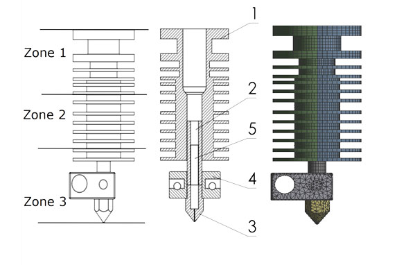
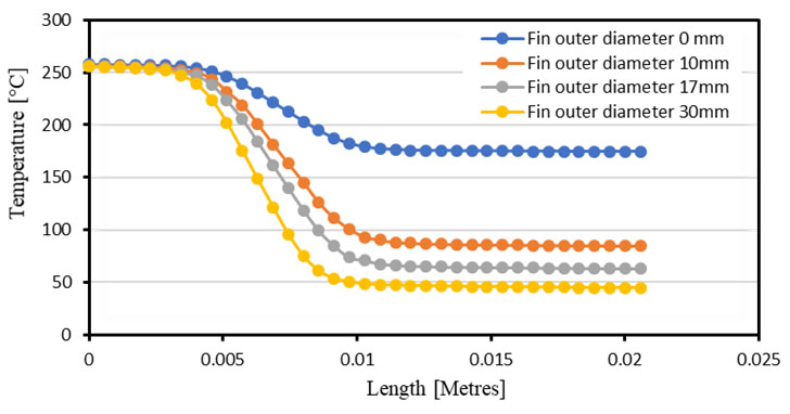
Simulation and modeling techniques for energy optimization
How Chat-GPT Can Assist Students in Academic and Career Development
Innovative Marketing Strategies for Event Managers
European Language Proficiency Tests: CEF vs. IELTS and TOEFL